Useful data gathered from geophysical survey techniques are instrumental in keeping our construction works safe, productive and efficient. With vast experience and proven track records in Singapore over the years, Ryobi-G is one of the geophysical survey companies which clients could trust.
Our geophysical survey techniques
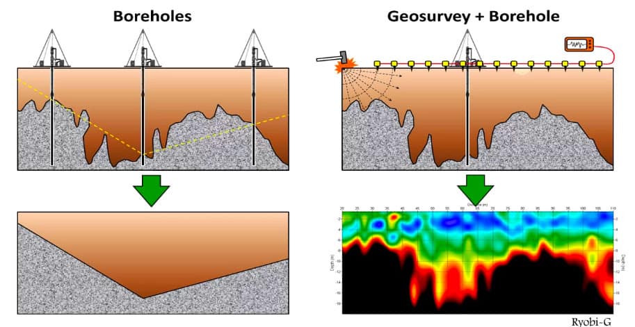
Our geophysical survey techniques focus on emphasising the contrasting physical properties between materials present below the ground surface. This is done on the ground surface using non-invasive, indirect methods to acquire data which are relevant and reliable to infer the profile below. Ultimately, useful information obtained through these geophysical techniques will help to minimise the no. of bore logs and trial trenches needed, before a conclusive interpretation of the profile could be achieved.
Maximum effectiveness
Ryobi-G understands that each project requirement is unique in its own way. Therefore, the team adopts a comprehensive approach in designing the most effective geophysical survey solution for each project requirement. This is done by integrating more than one method seamlessly into a single solution; a suitable combination of geophysical survey techniques. With the right people and the right techniques, Ryobi-G is committed to deliver accurate and reliable results.
A non-intrusive means of profiling the subsurface strata.
Safe
A cost-effective and time-saving approach when investigating a complex and/or large area.
Efficient
Some of the common applications of geophysical survey techniques
Detecting underground utilities Detecting unknown pile length Detecting buried structures Detecting cavity and loose soil Detecting landfills Detecting cavity Detecting bedrock Obtaining representative images of rock profiles Obtaining representative images of soil profiles
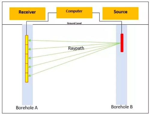
CROSSHOLE SEISMIC TOMOGRAPHY
Crosshole Seismic tomography, colloquially known as “Crosswell Seismic” or Crosshole Tomography is a relatively new technique we used to profile soil. Crosshole Seismic technique is used to determine compression (P) and seismic (S) waves travelling horizontally across medium on site, typically soft materials like soil. For this crosshole seismic technique, there are many devices to choose from to generate a high quality P and/or S wave. This specific method of geophysical survey can explore a depth up to 100m, measuring the gross velocity difference.
Crosshole Seismic Tomography requires minimally 2 boreholes with 70mm diameter PVC pipes. The receiver and probes are both inserted into the boreholes, followed by a shock generation by the source which is then received by the receiver. Data is collectively stored and analyze later.
Applications of Crosshole Seismic: 1) Foundation analysis 2) Insitu material testing 3) Soil profile/mechanics relative to seismic velocity 4) Locate the position of underground utilities
Similar to other kinds of geophysical surveys, Crosshole seismic tomography able to provide users with information in regards to the velocities of the ground, where horizontal layer and fundamentals assumptions can be made.
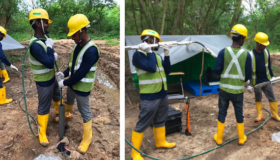
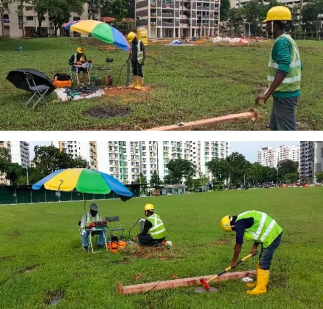
Placement of source and receivers into boreholes.
Schematic diagram of Crosshole Seismic Tomography.
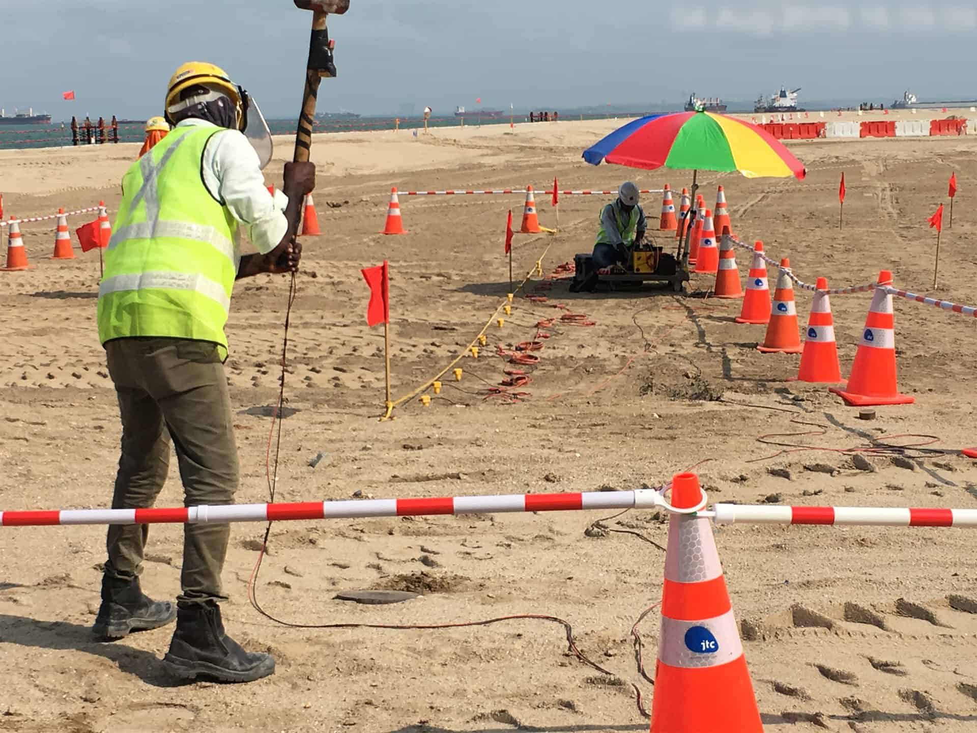
Workers can be observed hammering to generate waves from the seismic source for the test.
DOWNHOLE SEISMIC TEST
Similar to the Crosshole Seismic test, Downhole Seismic test determines the P and S velocity of the foundation. As opposed to crosshole seismic test, the seismic sensor will be lowered down to the borehole whereas the seismic source will be generated on ground level by hammering on a steel plate. . For P-wave generation, the hammering point shall be on top of the steel plate. For S-wave generation, the hammering point shall be on the side of steel beam. During data processing, the first time arrival of the P-wave / S-wave will be determined.
Applications of Downhole Seismic: 1) Foundation analysis 2) Insitu material testing 3) Soil profile/mechanics relative to seismic velocity
Data analysis is more straightforward as compared to crosshole seismic test and it lesser error prone.
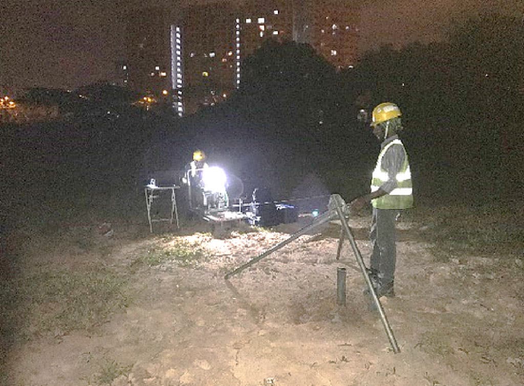
PS SUSPENSION LOGGING TEST
This method of PS suspension logging has been around over decades for the use of checking civil structures. P-S logging test (P-S suspension) uses a low frequency probe that measures the waves without using indirect excitation and it yields high resolution results as compared to other geophysical surveys.
With only the need for one borehole, PS suspension logging is also not affected by the path effects from the source, thus it yields more accurate results particularly for P-waves.
Applications for PS Suspension Logging: 1) Underground foundation and object detection 2) Civil structures 3) Soil properties 4) Dam Safety investigations
Site work for PS suspension logging test carried out at night to minimise surrounding noise for optimal result.
SCENARIOS THAT EMPLOYS THE USE OF GEOPHYSICAL SURVEY
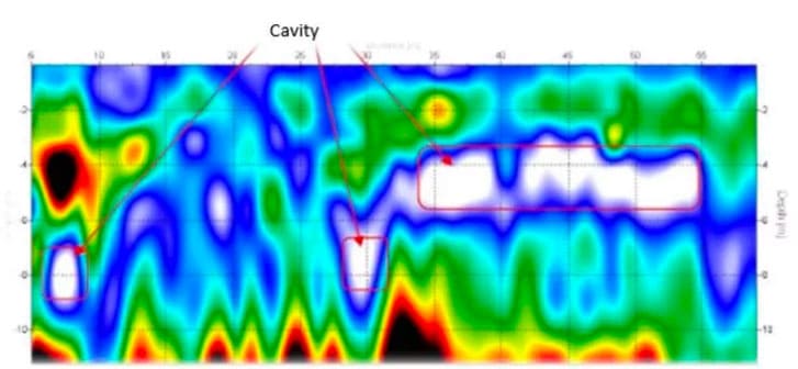
CAVITY DETECTION
Suitable for foundation / piling design Suitable for cable laying / pipe jacking design Suitable for earthwork design Depth of penetration subjected to the geophysical survey method Overcome the limitation of boreholes in detecting localised cavity Test results can be verified by mackintosh probe test
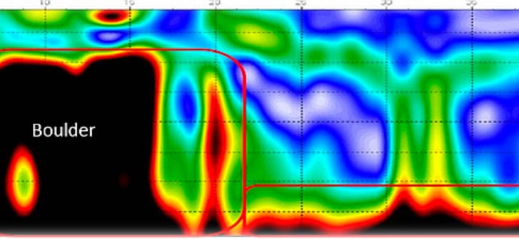
BOULDER DETECTION
Suitable for foundation / piling design Suitable for cable laying / pipe jacking design Suitable for earthwork design Depth of penetration subjected to the geophysical survey method Overcome the limitation of boreholes in detecting localize obstruction such as boulder, seawall, abandoned pile and etc.
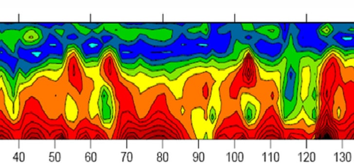
SOIL PROFILING
Suitable for foundation / piling design Suitable for cable laying / pipe jacking design Suitable for tunneling design Suitable for earthwork design Depth of penetration subjected to the geophysical survey method Combine with boreholes for better interpretation
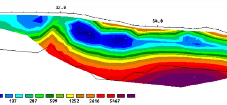
BEDROCK DETECTION
Suitable for foundation / piling design Suitable for cable laying / pipe jacking design Suitable for tunneling design Suitable for earthwork design Depth of penetration subjected to the geophysical survey method Combine with boreholes for better interpretation
INCREASING RELEVANCE
As Singapore’s public transport system and infrastructures are set to progress and increase in the foreseeable future, information from geophysical survey techniques will be essential for critical decision-making during the entire construction process. These information could help projects minimize rework and repair costs which may be incurred possibly due to, for example:
1) Inaccurate inference of the existing pile length 2) Misinterpretation of soil profiles 3) Unreliable existing information